Showing posts with label Tractor Part. Show all posts

Turbocharger Cleaning of CRDI Engine

Posted by Unknown on 13:24 with No comments


Turbocharger Cleaning of CRDI Engine.

To look inside the turbine was decided to disassemble and clean. Suddenly, what should be changed.

A cover, "lazy" exhaust gas "slow" air: Somehow, the turbine consists of three parts.

"The Snails" eponymous shellfish that resemble the name of a piece of iron.

Middle interesting part. These two impellers, as well as the East, the oil supply pipe is connected to the mount, bearings, axle, contains.

In the form of two clips that holds the clip open and a small screw (green rectangle) it to remove the "slow" to remove.


Next, vacuum diaphragm opening (held by two screws) and remove the hose.
Now, this part is nothing but rust and dust and can be removed carefully. Carefully, it is directly under the impeller, and it need not be because damage.
Black plaque clean the impeller.                                        "Lazy" to get out of the pump impeller not  only looked at the top and clean.                                       

Timing Belt Replacing of CRDI Engine

Posted by Unknown on 12:25 with No comments
Timing Belt Replacing of CRDI Engine
The shaking machine, which can be removed by jerking weak, in which case then, you, this item can take it, "hover" may be due to the small strain bad, all bolts opened and nuts.

Now you need to open the pad itself, his body screwed holds three large nuts. Opened three screws and take out the pillow.

We opened the crankshaft pulley (which is inside the dust cover gear, four-bolt is screwed on) and finish off.
And service as well as the belt comes off. The crankshaft gear cover, which (see photo below) at the 5 bolts holding the dust cover, untwist

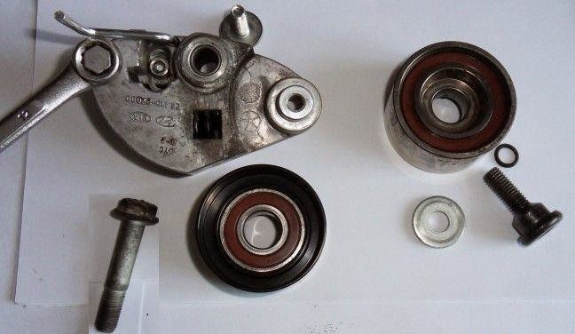
Parts which are hidden behind rollers, remove anything that can interfere with the extract. My issue is that the oil from the oil pump to the vacuum tube. Of copper gasket (circled in green growing oil supply pipe) Be careful not to lose.
(They are outlined in blue in the above image) Remove the four screws, engine support can be pulled out from the top. After removing parts from the engine looks like in the photo below, but in the back of the vehicle shall be:

Expose The Label Before Removing The Replaceable Parts


Mark on the upper sprocket on the same label, respectively, anti-cylinder head, crankshaft, can be attached in a position where an aircraft engine crank.

"15" button to take over and open up the tension pulley, then Allen bypass, remove them and remove the belt.

If you want ... usually, it turns off the pump belt replacement would be a more convenient opportunity, we just opened and the old coolant drain screw on the new one can . It is true that it is held by three bolts and a protective cover off, but it is not difficult to remove.

Label we put two new clips, cloth belt, labels are not moving out to make sure that the nail. The "bottom" tension roller (you can see in the photos below that need to pull the lock rod is bent), they crank the engine belt press, moved out of the label are not sure . If you moved, tension roller available for Ellen on her head (her picture circled in black) take can return to its original position, and the right cover, and then belt fine to make.

The label is displayed correctly and the tensioner (red circled) hex bolts, tightening belts are tensioned, then it will correct its position and belt teeth between the "jump" will not allow.
As a result, bypassing the tensioner in place is exactly. The next time I buy a two-pass effect, in addition to a lot more confidence, it actually was planted that little more secure feeling.

Stored in reverse order. I'm having difficulty getting dressed belt service. All of rollers mounted on the crankshaft pulley and throw a part, hold and crank turning the belt, the belt did not work the first time, put on. How to parse a little time with a picture will be taken. The camera was not changed and is not for images. Which is not explained clearly ask!

Cars which use the same parts ballot:

Hyundai Accent [AW]                                                  Hyundai Getz [BJ]
Hyundai Matrix [BE]                                                    Kia Carens [FJ]
Hyundai Santa Fe [BB]                                                KIA CERATO [CD]
Hyundai TRAJET [EC]                                                Hyundai Accent [B]
Hyundai TRAJET [FO]                                                Hyundai Accent [BG]
Hyundai Tucson [BH]                                                   Hyundai Accent [LC]
HYUNDAI ELANTRA [CG]                                      HYUNDAI ELANTRA [CA]

TD Series gear drive

Posted by Unknown on 10:56 with
TD Series gear drive
Design for factory collection OEM Screw Conveyor Application


Most of its products due to the custom nature,To discuss your project please contact our sales team.Along with preparing for the quantity purchased will affect the price of options chosen.Our trained professionals guide you and can provide an accurate quote.

     
Factory gear drive, motor, mountain, sheaves, and with beltguard collection.
     
Shipped ready to install on conveyor
     
Dorris TD Series part numbers, motor horsepower, RPM Final Drive Identification
     
The size of the shaft, and provide customer products (ie motors and sheaves).
     
Desired speed is not shown, consult factory.
     
CEMA standard trough TD drives fit and finish is standard performance packing gland.
     
TD drives are SF = 1.5 AGMA Class II classification (SF = 1.4) and the V-belt.
     
Standard motors 1750 RPM, TEFC and NEMA frame sizes are standard.


 Belt Guard DetailTD series designed custom belt guard.Power of 16 gage carbon steel hinged door for easy access with coated safety yellow.Dorris V belt provides selection criteriaLoading a V-belt drive rated capacity of at least 1.25 with a service element is used with a gear drive motor power ratings using a nominal 1.5 Service element will be based - 1.5 or AGMA Class II service. The minimum service factor of factors when serving high-gear drive gear drive should be picked up from that match.Sheave Type: assembly / disassembly with tapered bushings for ease and a minimum of 2 grooves to be used only with sheaves. Sheaves with a groove bore size and will not be allowed.Belt Type: V-belt cross sections from one extreme (3V, 5V, or 8V) or classical music (B, C or D only) can either be design. Take a look at the selection of heat dissipation design would be a tooth or wrap.Downside: belt drive speed reduction final drive. 2.3 / 1 shall not exceed a maximum speed greater than 20 RPM. Because of this low wrap angle to prevent excessive belt tie will work.For more information Partpk company.

TRC Series Shaft Mount

Posted by Unknown on 09:55 with
TRC Series Shaft Mount
 
Gear drive a low cost of ownership, reduced maintenance and downtime, with no belt slippage risk or more efficient, and an easy drive package provides a unique solution, and to change the speed of the belt driven with the motor mount standard can be.
TRC gear drives a motor adapter plate, torque arm assembly, said key input shaft to the shaft. Also need a bushing kit.
Options include:


              Facing mounting holes
              Curved jaw coupling
              The face of Motor Adaptor
              Backstop Kit
              Optional Torque arm Format

TLC Series Gear Drive

Posted by Unknown on 10:05 with

TLC Series Gear Drive
Screw Conveyor Drive Shaft C-face with removable drive

TLC Series gear drive motor adapter plate, a shaft kit and a Screw Conveyor drive with adapter kit included. CEMA Standard Adaptor Dorris way unless customer requests trough end adapter is assumed.
Options include:

      C-face motor adapter
      Curved jaw coupling
      High performance packing gland
      Grease / air purification gland packing
      303 stainless steel output shaft
      Three holes are drilled shaft Ouptut


TR Shaft Mount Gear Drive

Posted by Unknown on 10:56 with
 TR Shaft Mount Gear Drive

Dorris is the third generation of the product line shaft mounts. This last product offerings offer the same design integrity and reliablility but separated from the rest of the design industry not only determines Dorris. TR Series offers:

More ratio options - three ratios, 30:1, 35:1 and 40:1, are new and only available from Dorris. Select a drive system to allow for several new options. They are low output speed, high speed, low cost motors, tiny, less expensive sheaves and a face gear drive motor within a substantial proportion of straight couples. 250:1 and 200:1, respectively, at 415 and 507 offer the triple reduction ratio, as well as double reduction gearing.

Tight design - a shaft-mounted gear drive to one of the most criticial Dimensions are based on the length of the shaft. Dorris TR design a narrow "the Thru-Bore" Dimension, Open (motor) that a bushing mounts by design, and partly through the drive gear on the drive shaft that needs to provide require. With these features, TR design leading competitor only requires about half the length of the driven shaft.

For Immediate Release - Quick release of tapered bushing, bushing install any comparison is easy to remove from the system maximum gripping power driven shaft that is compliant with flexible arm and threaded collar. Binding, cracks or fretting corrosion, is designed to avoid local welding and other problems in the design of many bushing.
 Motor mounts - just 3 Size 7 model, 107-315 are required. TR series shaft mounted gear drives easily CEMA Dorris or trough ends can adopt either a TL Series Screw Conveyor can turn to drive.
 Conversion Kit - A drive shaft cut and the trough end adapter kit is required as well as a TL, a TR / TL conversion kit, a TR to change.
 U.S. Made and low investment - TR products, versatile, efficient and cost-effective. Fully built with American workers and American manufactured in a U.S. plant.

TL Screw Conveyor Gear Drive

Posted by Unknown on 12:40 with

 TL Screw Conveyor Gear Drive

The TL Product Line offers the same design integrity and reliability of previous product offerings but this new design sets Dorris apart from the rest of the industry.  The TL Series consists of:
Component Gear Drive -- Equal to the TR Gear Drive, adding a gear drive adaptor and removing the Torque Arm Assembly.  
Drive Shaft Kit --  The TL Drive Shaft Kit contains a removable shaft, locknut, lockwasher and key.  TL Drive Shafts have a tapered output end to avoid binding.
Trough End Adaptor Kit -- The Trough End Adaptor Kit contains the Trough End Adapter and Packing Gland Assembly.  Dorris Trough Ends are also available.
Conversion Kit -- To Convert a TR to a TL, a TR/TL Conversion Kit, along with  drive shaft kit and trough end adapter kit is required.
Options -- Options include Motor Mount, High Performance Packing Gland, Grease/Air Purge Packing Gland, 303 Stainless Steel Output Shaft and Three-Hole Drilled Output Shaft.
American Made & Less Investment -- The TL product is versatile, efficient and cost-effective.  Completely American Made with American Workers and produced in an American Plant. 

Dorris Base Type Gear Drives

Posted by Unknown on 11:01 with No comments
Dorris Base Type Gear Drives
Features and Benefits:
  • Broad Ratios (1.5 to 250:1) - Sizes 900 to 10000
  • Torque Ratings to 240,000 in-lbs output
  • Multiple shaft arrangements and mounting positions
  • Unique sizes under 5800
  • Tapered roller bearings throughout
  • Standard, Modified and Custom drives
  • Designed for minimum bearing and gear life (L10) of 10,000 hours under rated load.
  • Parallel shaft gear drives support gears between bearings. There is no overhung pinion as found in concentric gear drives.
  • There are many ratios available for each model; not all are mentioned in the catalog or even on this site. No engineering charges if the ratio has been previously designed.
  • Customizing of input and output shafts for customer needs is common and cost effective. No engineering charges if the shaft has been previously designed.
  • Ductile Cast Iron and Fabricated Steel Housings are available and will be quoted upon customer request. Ductile Cast Iron standard on 9900 and 10000 Models. Fabricated Steel Housings standard on 12000 Model.
  • Top Motor Mount provides means for V-Belt input. This minimizes the floor space required and provides a means to adjust the ratio for an exact output speed.
  • Bedplates provide a common mounting for motor and gear drive. Optional Adjustable Bedplate Base allows movement of output to tension chain drive or alignment of output shaft for a coupling.
  • Options available include Oil Sump Heaters, Non-Contact Labyrinth Oil Seals, Ceiling and Wall Mounting. Complete custom parallel shaft gear drives using stock components reduces cost and lead time.

Technical Information About Helical Gears

Posted by Unknown on 13:15 with 2 comments
Technical Information About Helical Gears

HELICAL GEARS when used on parallel shafts are similar in usage to spur gears. Where velocities exceed 1000 feet per minute, helical gears provide a stronger, smoother running gear train.
This type of stock gearing is furnished in 45° helix angle. Materials available are hardened steel, steel, stainless, aluminum, bronze, nylon and non-metallic (phenolic).
End Thrust is developed by helical gears, but this may be overcome through the use of thrust washers or other suitable types of thrust bearings.
When used on shafts at right angles these gears are commonly known as “spiral gears”. In this application they have only point contact between the teeth and are, therefore, not suitable for transmitting any appreciable amount of horsepower.
PartPk also sells gear tooth measuring devices called GEAR GAGES! Gear Gages reduce mistakes, save time and money when identifying and ordering gears. These pitch templates are available in nine sets to identify all the standard pitch sizes: Diametral Pitch “DP”, Circular Pitch “CP”, External Involute Splines, Metric Module “MOD”, Stub Tooth, Fine Pitches, Coarse Pitches and Unusual Pitches. Refer to the section on GEAR GAGES for catalog numbers when ordering.

Technical Information About Spur Gears

Posted by Unknown on 09:08 with No comments
Technical Information About Spur Gears

Spur Gears are the most popular form and the most efficient type of gearing for the cost when transmitting power and uniform rotary motion from one parallel shaft to another. Within the limitations of center distance, spur gears provide a positive, constant speed drive, the speed of which may be increased or decreased by increasing or decreasing the number of teeth in the driving gear.
Spur Gears may be operated in a “gear-train” of two or more gears but they must all be of the same diametral pitch and pressure angle. Gears with 14-1/2° pressure angle will not operate with those cut to 20° pressure angle.

RUSH GEARS inc. SPUR GEARS are available in eight materials: STEEL, HARDENED TEETH, CAST IRON, BRONZE, STAINLESS STEEL, ALUMINUM, NYLON, NON-METALLIC PHENOLIC. Gears made of custom materials to customer specifications can be promptly furnished.
Pitch line velocity of metallic gears should not exceed 1200 feet per minute. Where noise is a factor, but higher speeds cannot be avoided it is recommended that a nylon or non-metallic gear be used and operated up to speeds of 2400 feet per minute preventing much of the noise and vibration caused by metal to metal contact.
All critical surfaces of RUSH GEARS inc. SPUR GEARS are precision machined to close tolerances. Change Gears, Pinion Wire, Stem Pinions, Internal Gears and Rack are all spur gears of various types able to operate together since each has the same straight involute tooth form.
RUSH GEARS also sell gear tooth measuring devices called GEAR GAGES! Gear Gages reduce mistakes, save time and money when identifying and ordering gears. These pitch templates are available in three sets to identify all the standard pitch sizes: Diametral Pitch “DP”, Circular Pitch “CP”, and Metric Module “MOD”. Refer to the section on GEAR GAGES for catalog numbers when ordering.

Tractor Lower Link

Posted by Unknown on 13:58 with No comments
 Tractor Lower Link

We are engaged in offering a wide range of supreme quality Tractor Lower Link in the market. Manufactured using superior quality raw material, these products are designed by a team of experts. The Tractor Lower Links offered by us are highly demanded in the market for their availability in different sizes, grades, surface finishes and designs.


Following are the features of these products:


  • Durable standards
  • Dimensional accuracy
  • Corrosion resistant finish

Tractor Bush

Posted by Unknown on 13:49 with No comments
 Tractor Bush

We are instrumental in offering a wide range of  Tractor Bush to the esteemed customers. These parts are especially designed by a team of our professional designers in compliance with the international quality standards. Moreover, we customize the products as per the clients' specific requirements, which helps us in attaining their maximum level of satisfaction.


Following are some of the quality attributes of these products:


  • Accurate dimensions
  • Durable standards
  • Ease of maintenance

Fabricated Tractor spare parts

Posted by Unknown on 11:34 with 1 comment
Fabricated Tractor spare parts


We are considered as one of the recognized organization engaged in offering a wide range of  Tractor Spare Part to the customers. These products are made available in varied grades, surface finishes, sizes and other specifications to meet clients' varied requirements. Moreover, after checking these products on certain quality parameters before their dispatch to the clients' end. Our range of spare parts is extensively used in automobile industry, thus, are highly demanded by the clients.

Starter, 12V, CCW, 16T, (Reman)

Posted by Unknown on 08:46 with No comments

Additional Information

Did your United Technologies starter give up on you? We're here to help. Our replacement 0196540MO30SM-R starter is built tough and fits the United Technologies 1 CYL 5/6/8/10//11 HP ENG engine properly. We strive to keep your United Technologies running for the long term, which is why we sell quality parts that are built to last.
United Technologies parts are expensive and thats why we sell starters direct at significantly lower prices than your United Technologies dealer. You can save up to 70% with TractorJoe.
Price is just one part of the equation though- quality matters too. We don't want you replacing your starter more than you need to, which is why we back our parts with an industry leading warranty. Even if your 1 CYL 5/6/8/10//11 HP ENG is not your main piece of equipment, TractorJoe knows that having it up and running is always important.

 Description & Notes

Part # 0196540MO30SM-R
Package Quantity 1
Group Ignition & Electrical Parts
Subgroup Starters & Related Parts

Product Fit

Fits United Technologies 1 CYL 5/6/8/10//11 HP ENG Engines      

Vehicle rear windshield wiper device

Posted by Unknown on 10:33 with No comments
Vehicle rear windshield wiper device

Abstract
A wiper blade is pivotally coupled to a main gear rotatably mounted via a wiper arm and abuts the rear window of a vehicle. Rods first and second gear are provided in spaced parallel coplanar flanking the main landing gear. The first and second worm gears are fixed to first ends of the first and second screw rods, respectively, each on a side of the master gear. A supporting device pivotally mounted support rod gear with the first and second worm gears on diametrically opposite sides of the main gear. An actuator is coupled to the transmission rods for rotating the first and second worm gears. An electromagnetic control device is coupled to the support device for reciprocating the first and second worm gears in mating relationship with the main gear thereby rotating the main gear alternately clockwise and counter-clockwise and move the sheet wiper in a wide arc.
DescriptionBackground of the InventionThe present invention relates to a windscreen wiper device of the vehicle. More particularly, the invention relates to a vehicle rear-window wiper device for a vehicle having a rear window.Objects of the invention are to provide a device of the vehicle rear wiper simple structure, which is inexpensive in manufacture, easily installable in new and existing vehicles, and functions efficiently, effectively and reliably to provide ample windshield washer function arc to the rear window of a vehicle.BRIEF DESCRIPTION OF THE DRAWINGSIn order that the present invention may be readily carried into effect, will now be described with reference to the accompanying drawings, in which:. Figure 1 is a view of a rear window of a vehicle that uses the wiper device of the invention;. Figure 2 is a perspective view of an embodiment of the rear windscreen wiper device of the vehicle of the invention;. Figure 3 is a circuit diagram of the rear windscreen wiper device of the vehicle of the invention;. Figure 4 is a top view of the embodiment of FIG. 2, and. Figure 5 is a schematic diagram explaining the operation of the embodiment of FIG. Two.DETAILED DESCRIPTION OF THE INVENTIONThe rear windscreen wiper device for vehicles of the invention is for a vehicle 1 having a rear window 2 (Figs. 1 and 2).Wiper device of the invention comprises a main gear rotatably mounted 3 (Figures 2, 4 and 5).A wiper blade 4 is pivotally coupled to the main gear 3 via a wiper arm 5 (Figs. 1 and 2) and abuts the rear window 2 of the vehicle 1. First and second gear rods 6 and 7 (Figure 2) are provided in a parallel spaced relation flanking substantially coplanar with the main gear 3.The first and second worm gears 8 and 9 (Figs. 2, 4 and 5) are attached to first ends of the first and second gear rods 6 and 7, respectively, each on a corresponding side of the main gear 3.A support member pivotally mounted crank or 10 (Figures 2, 4 and 5) supports the gear rods 6 and 7 with the first and second worm gears 8 and 9 on diametrically opposite sides of the main gear three.An actuator is coupled to the gear rack 6 and 7 for rotating the first and second worm gears 8 and 9 in the same direction around the axes of said gear rods. The actuating device comprises a motor 11 (Figs. 2 and 3). A drive gear 12 (Figures 2, 4 and 5) is coupled to and driven by the motor 11. A first planetary gear 13 is fixed to a second end of the first rod 6 and gear coupled to and driven by the drive gear 12, as shown in FIGS. 2, 4 and 5. A second planetary gear 14 is secured to a second end of the second rod 7 and gear coupled to and driven by the drive gear 12, as shown in FIGS. 2, 4 and 5.An electromagnetic control device is coupled to the support member or bell crank 10 to reciprocate the first and second worm gears 8 and 9 in mating relationship with three main gear thereby rotating the main gear alternately clockwise and to the left and move the wiper blade 4 in a wide arc as shown in Fig. 1. The electromagnetic control device comprises a control link 15 (Figures 2, 4 and 5) attached to the bell crank 10 at its center and having first and second opposite ends 16 and 17 (Figure 2). A first solenoid device 18 is provided in operative proximity with the first end 16 of the control connection 15 (Figures 2, 4 and 5). A second solenoid device 19 is provided in operative proximity with the second end 17 of the control connection 15 (Figures 2, 4 and 5). The first and second solenoids 18 and 19 are shown in Fig. Three. As shown in the figures. 2 and 3, a pair of switching devices 20 and 21 are operated by the wiper arm 5 for alternately activating the first and second solenoid devices 18 and 19, respectively. An on-off switch 22 controls energization of the motor 11 from an electrical source 23 which may comprise the battery of the vehicle 1.In operation, when the wiper arm 5 is at one end of its arc and the contacts of the switching device 20, the first worm gear 8 is moved into engagement with the main coupling 3 first solenoid activation 18, and the wiper arm is rotated by said main gear in a clockwise direction until it reaches the other end of its arc and contacts the second switching device 21. When the wiper arm 5 in contact with the second switching device 21, the second worm gear 9 is moved to mating engagement with the main gear 3 by activation of the second solenoid 19 and said main gear arm moves the blade in a counterclockwise direction until it returns to the end of the arc adjacent to the first switching device 20. The cycle then repeats.While the invention has been described by a specific example and in a specific embodiment, not to be limited thereto, for obvious modifications will occur to those skilled in the art without departing from the spirit and scope of the invention.

Reversible speed reduction mechanism

Posted by Unknown on 11:38 with No comments
Reversible speed reduction mechanism


Abstract
A speed reduction mechanism reversible for use with electric hand tools comprises a pair of juxtaposed epicyclic gear train mounted on a common carrier, to independently engage a pair of cage or ring gears. The cages can be alternately locked or released from an outer casing to perform bidirectional transmission of rotational power. The complete reversal mechanism is in a generally cylindrical body suitable for mounting between a conventional unidirectional motor and gear head or powered device. Output rotation forward or reverse is selected by moving a control button located on the periphery of the reverse. Reduced velocity in the range of 3 to 5 to 1 can be achieved through this mechanism.

DescriptionBackground of the InventionThe invention relates to a speed reduction mechanism for reversible use with hand-held power tools and more particularly to a reversing mechanism for use with tools energy production line having a motor and gear head separable it also provides a reduction in speed three to 1:00 to 12:55 and a proportional increase in output torque concomitant.The increasing reliance of the method of the production line of manufacturing has created a dependency of equality in lightweight portable power tools for use by assembly personnel in the manufacturing process. The vast majority of these tools are powered by compressed air or electricity. Various devices, such as gear trains, and ratchet mechanisms pulse devices can be attached to relatively simple high rpm motors to provide energy in the form required by an assembly operation indicated.One of the most common requirements of these power tools is the ability to reverse the direction of the unit in order to facilitate removal of a threaded fastener that may have been improperly inserted or which must be removed in order to remove other components.The electrically powered tools, directional control is a tricky problem. It is well known that by simply reversing the polarity of the electricity to the motor windings is some directional control effect and this can be accomplished by conventional switching means. However, seldom appreciated that the rotational speeds of these motors may be as high as 15,000 RPM, and that the sudden change of the motor driven elements undergoes a tool to severe shock which considerably shortens its lifetime. Second, the current increase associated with investment EMF motor reversing switch requires a heavy duty too. Unfortunately, a circuit which exhibits the necessary durability is generally bulky and often fatiguing to the operator of the tool due to its high activation force.In the case of pneumatic engines, the most commonly invoked to provide bidirectional rotation is a vane motor that has two input ports, arranged symmetrically on opposite halves of the vane motor chamber and an exhaust port common positioned midway between the ports. Air that enters a port of entry and exits through the common exhaust port engine causes the air to rotate in one direction while the air entering the other port of entry and exit of the exhaust port common causes motor rotation in the opposite direction. This type of air motor reverse has a drawback. Since the air has to enter and exit the vane motor to compensate less than 180 degrees, the expansive force and thus the power produced by the air motor is less than that which can occur in an engine in the conventional way that the radial separation of the input and output ports from the effective use of the expansive force air over approximately 240 degrees. Therefore, if the output of an air motor must be bidirectional, a certain amount of output power must be compromised to achieve this.The alternative to using a bidirectional air or electric motor in a hand tool is the incorporation of an independent reversing mechanism into a tool that has a unidirectional motor. In general, these devices have the power output lower than a unidirectional tool. In this case, the power loss is due to additional gear in the reverse. Reversing Such mechanisms also generally add substantially to the weight of the hand power tool. In the work of the production line, where an operator can lift and move the tool continuously for several hours, any additional weight greatly increases operator fatigue. Moreover, the tool size is also an important consideration, as it often is necessary to operate the tool in the structure being assembled, such as an automobile. A bulky tool that includes the ability of investment required in an application may, however, be unusuable because it can not participate or can not be easily manipulated to engage the closure or other device that is intended to mount due to limited space in which to function.If a production process requires slow rotation, the mechanism can be even more complex. Preparing addition needed to produce bedirectional output rotation may be necessary and the size and weight of the rollback mechanism then may increase to a point where the tool is unsurpassed for production line use.SUMMARY OF THE INVENTIONThe invention comprises a speed reduction mechanism for use with reversible electric hand tools which have a pair of epicyclic gear trains juxtaposed mounted in a vehicle independently engage a pair of cage or ring gear. The cages can be locked to or released selectively to an outer housing for effecting bidirectional output tool supply air stream. A reduction ratio in the range of 3 to 5 to 1 that can be different in the forward and reverse directions slows the rotational speed of the drive motor while effecting an increase in torque. The reversal mechanism is contained in a generally cylindrical housing having a diameter approximately equal to the engine to which it is mounted and which includes a control button that can be moved to the front or rear of the cylindrical housing by the operator to select the rotational direction of the output.The only speed reduction mode or forward operation, the first cage is locked to the outer casing and the second cage is free to rotate. The first epicyclic gear train is driven from the input shaft and rotates inside the first cage. The carrier on which is mounted the first epicyclic gear train is connected directly to the output shaft that transfers rotational power out of the mechanism. Operating in the back, how to accelerate the reduction, the second cage is locked to the first cage housng and is free to rotate. The second epicyclic gear train comprising two pairs of meshing gears one of each pair is indirectly driven by the input shaft, the second gear of each pair engaging the cage closed. The second epicyclic gear train thus rotates in the reverse direction of the input shaft and causes a reverse rotation as the carrier and the output shaft.It is therefore an object of this invention to provide a speed reduction mechanism for use with reversible electric hand tools.It is a further object of this invention to provide a speed reduction mechanism reversible, so it can be retrofit to existing electrical hand tools separable between the motor and the drive head.It is yet a further object of this invention to provide a mechanism of this type in a compact, light weight that does not add substantially to the weight and dimensions of the power tool.It is yet a further object of this invention to provide a speed reduction mechanism reversible, so that has a structure that is easy to control and positively operable.It is yet a further object of this invention to provide a reversible speed reduction mechanism, which incorporates both equal and unequal forward gear ratios and the reverse.BRIEF DESCRIPTION OF THE DRAWINGS. Figure 1 is a top plan view of a speed reduction mechanism according to the present invention in place on a power hand tool;. Figure 2 is a side elevational view in full section of a speed reduction mechanism reversible according to the present invention, taken along line 2 - 2 of FIG. 1;. Figure 3 is an end elevational view in full section of a speed reduction mechanism reversible according to the present invention taken along line 3 - 3 of FIG. 2;. Figure 4 is a full sectional elevation of a mechanism reversible speed reduction according to the present invention taken along line 4 - 4 in Fig. 2, and. Figure 5 is a perspective exploded view in partial section of the components of a speed reduction mechanism reversible according to the present invention.DESCRIPTION OF THE PREFERRED EMBODIMENT

Referring now to FIG. 1, a speed reduction mechanism reversible according to the present invention is generally designated by reference numeral 10. The mechanism 10 is adapted to be positioned between a motor housing 11 and an outlet head 12 in a conventional power tool. The mechanism 10 is entirely contained within a cylindrical housing 13.Referring now to FIG. 2, the assembly between the motor housing 11 and the outlet header 12 is facilitated by female threads 14 and male threads 16 on housing investment mechanism 13 which engage matching male thread 15 and the female thread 17 in the housing 11 and head 12 respectively. An input shaft 18 transfers power from the motor mechanism 10. The input shaft 18 includes gear teeth 19 along a portion of its length and tapers near its terminus to a reduced diameter portion 20. The reduced diameter portion 20 seats within an axial bearing aperture 22 is formed within a gear holder 23. The gear holder 23 is disposed concentrically about the input shaft 18 and also includes a recessed portion 24 which is engageable by an engagement surface toothing (not shown) on an output shaft 25 is illustrated in Fig. 1. The input shaft 18 and carrier gear 23 are rotatably positioned within the housing 13 and are maintained in coaxial alignment by two anti-friction bearings 26. Antifriction bearings 26 may be ball bearings or other suitable means. The input shaft 18, the gear carrier 23 and antifriction bearings 26 are kept in proper relative longitudinal alignment within the housing 13 by spacers 27 and retaining rings 28. The rings 28 are seated in the circumferential grooves 29 in the input shaft 18 and the gear carrier 23.Referring now to FIGS. 2 and 3, the investment mechanism 10 is seen to include a first planetary gear set or idler 31. Each intermediate gear 31 is fixed to an axis structure 32 which is mounted on pairs of apertures 33 in the carrier 23 about axes parallel to the drive shaft 18. As seen in Fig. 3, idler gears 31 engage the teeth of gear 19 in the input shaft 18 and the gear teeth 35 on the inner surface of a circumferential planetary gear cage 36. The gearbox 36 is positioned concentrically within the housing 13 and bears axially against an annular thrust bearing assembly 37. The cage 36 also includes a plurality of teeth 38 radially arranged on a surface protruding outward adjacent to the thrust bearing assembly 37. The profile of the teeth 38 can be any one of a series of conventional gear profiles subject to common connection engagement softer compared to the minimization of the axial forces that tend to disengage resolved said teeth.Referring again to FIG. 2, the mechanism 10 can also be seen to include a brake for inhibiting rotation of ring 41 concentrically disposed within the housing 13. The brake ring 14 contains a plurality of teeth 42 on its face adjacent teeth 38 which are of similar profile and mate therewith. Similarly, the opposite face of the brake ring 41 includes a plurality of teeth 43. The brake ring 41 further includes a radially extending protrusion 44 that passes through an aperture 45 in the housing 13 and is equipped with a control knob or button 46 which is manually positionable at a position forward or backward by the tool operator.Referring now to FIGS. 2 and 4, shaft 32 structures which are mounted on the first pair of intermediate gears 31 extend axially forward inside the housing 13 and mounting a second pair of idler gears 50. The intermediate gears 50 represent an average of the second epicyclic gear train also containing a third pair of idler gears 51. Each intermediate gear 51 is placed in a short axis 52 and an anti-friction bearing 53 between the intermediate gears 51 and the axle stub 52 minimizes friction between those components. The stub shafts 52 are mounted on pairs of aligned apertures 54 in the carrier 23. The intermediate gears 51 engage the intermediate gear 50 and the gear teeth 55 on a second gearbox 56. The gear cage 56 is positioned concentrically within the housing 13 and is coaxial with the input shaft 18. An anti-friction assembly 57 is disposed between an axial end of the cage 56 and the shoulder section of the housing 13. Cage 56 further includes a plurality of teeth 58 radially arranged on a surface that protrudes outwardly from the cage 56. Teeth 58 are engageable with teeth 43 disposed on the adjacent radial surface of the brake ring 41.Referring now to FIG. 5, the spatial positioning of the reverse elements can be seen clearly. Note that the shaft 18 including the gear teeth 19 and the reduced diameter portion 20 is mounted from the left end of the carrier 23 and the seats at the inlet opening 22. Similarly, the rollers 31 on the shaft structure 32 are seated on the carrier 23 between the gear teeth of the input shaft 19 and the gear teeth 35 on the inner surface of the gearbox 36. The second epicyclic gear assembly 50 includes the intermediate gears and the idler gears 51 which are located within the carrier 23. The rollers 51 are positioned at the heel of the shafts 52 and mesh with the rollers 50 and the gear teeth 55 on the inner surface of the cage 56. Teeth 42 and 43 on the brake ring 41 to selectively engage and disengage the engagement teeth 38 and 58 in the boxes 36 and 56, respectively.The operating mechanism 10 may be better understood by reference to FIGS. 2 and 5. The only speed reduction mode or running forward, the brake ring 41 moves to the left as shown in FIGS. 2 and 5. The cage 36 is therefore locked in the housing 13 while the second cage 56 is free to rotate. The gear teeth 19 on input shaft 18 driving the intermediate gear 31 rotating in the opposite direction. Rollers 31, however, must rotate against the gear teeth 35 on the inner surface of the closed cage 36 and thus force the carrier 23 to rotate in the same direction as the input shaft 18, but at a reduced speed .Operation mode reverse speed reduction is similar. The brake ring 41 moves to the right as illustrated in Fig. 2, the unlocking of the locking cage 36 and the cage 56 to the housing 13. The rotary motion is imparted to the shaft structure 32 through the intermediate gears 31, the gear teeth 19 on the input shaft 18. Intermediate rollers 50 power transmission to the second rollers 51 which are in engagement with the gear teeth 55 on the inner surface of the cage 56. Since the rollers 51 are engaged with the cage 56 in a manner similar to the engagement of the rollers 31 in the cage 36, but are rotating in the opposite direction to roller 31, the support 23 is forced to rotate in the opposite direction to the drive mode (a reduced speed) of the operation. Again, since the output of the mechanism 10 is derived from the carrier 23, it is evident that a reduction in the rotation speed and a change of direction is achieved.Regarding the range of reduction rates, various combinations of gear teeth can be incorporated into the reverse gear ratios to produce in the range of approximately 3 to 5 to 1. For example, the cages 36 and 56 can include gear teeth 42 on its inner surface, the gear teeth 19 on the input shaft 18 can be 12 in number, 31 May rollers have 15 teeth, the rollers 50 may have 9 tooth, and the rollers 51 may have 12 teeth. In the forward mode of operation of this combination results in a reduction gear of the speed of 4.5 to 1. In the inverse mode of operation is effected a reduction in speed from 4.833 to 1. Therefore, it is clear that the reduction ratios for forward drive and reverse need not be equal.As a second example, the number of gear teeth on the intermediate gears 31 can be increased to 14, while using the same number of gear teeth in all other elements. This results in reduction of the same feed rate of 4.5 to 1, while reducing the speed in the reverse mode will be from 4.444 to 1. As noted above, various combinations of gear teeth and various gear ratios produced pulleys in the range from 3 to 1 to 5 to 1.The above description is the best mode devised by the inventor for practicing this invention. However, the invention should not be construed as limited by the foregoing description. It is evident that various other embodiments incorporating modifications and variations will be obvious to one skilled in the art to which the invention pertains. Such obvious variations are included and the invention limited only by the spirit and scope of the following claims.